First things first, we need to figure out how to drive and read the spectrometer. There are two key diagrams to consult - the suggested application and the timing diagram.
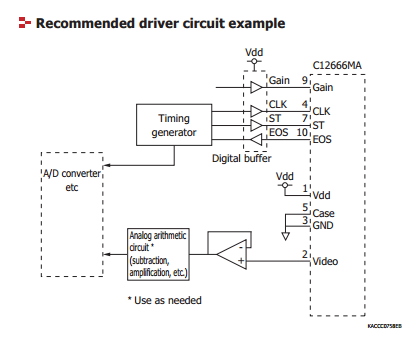
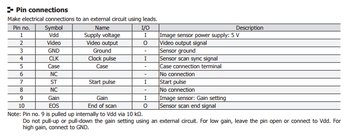
The application diagram shows several key signals, some of which the meaning isn’t clear at first. After reading through the rest of datasheet, you can generally make out the following pins:
- Video - the spectrometer is like a 2d camera - it is an image sensor in a line after all. Video represents the actual output, as an analog signal, of the sensor.
- Gain - an input, to select the gain
- CLK - A clock input
- ST - A start trigger
- EOS - an end of line/scan indicator - when this signal changes, you reached the end of the sensor
Now, the timing diagram:
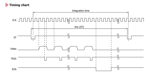
There are a few takeaways:
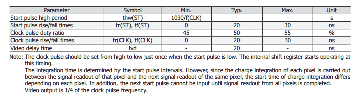
- The sensor needs a clock signal, of a fixed frequency. Based on the datasheet, it need not be very high (0.25 - 200kHz).
- The sensor has an integration time, that is, how long it is accumulating light in its internal cells before allowing them to be read out. This is the period between ST pulses, which means the sensor stores the light levels into a buffer on readout.
- A new video pulse is available every 4 clock cycles. The video pulse is available by the second low clock transition.
- When the sensor is done, it drops EOS for 4 clock cycles.
So, what do we need to use this?
- An A/D. We need to be able to take the voltage from the VIDEO pin (from 0.15-3.3V) for every wavelength as we run the CLK pin. Ideally, this is a 14-16 bit A/D.
- A timing generator where we can produce a CLK rate, and a ST pin timer, at up to 800kHz. We also need to be able to read the A/D at 200kHz, synchronized with the above clock.
- A buffer op-amp - as the output of the sensor is very high impedance, and many types of A/Ds put a large load (relatively) on the signal, we need to provide a simple voltage follower.
In the next installment, I’ll look at some interface potentials.