Controlling pressurized carbon dioxide (CO2) delivery into a Calcium reactor or into a planted tank with precision can be fraught with problems. The conventional mechanism is to use a needle valve after a pressure regulator - this design is very finicky to adjust for low flow rates and has a tendency to drift over time, meaning your carefully controlled delivery is now out of whack. In addition, if you use a pH controller driving an AC solenoid valve, the valve actuation can be quite audible.
There is a commercially available CO2 control system - the CarbonDoser/AquariumPlants doser - which uses a standard regulator but does not use a needle valve to adjust flow. Instead, it uses an internal micro-solenoid to deliver small bursts of CO2 at a user selected frequency into the system. While its not a true volumetric flow (the amount of CO2 delivered is still dependent on the back-pressure of the system, so its not truly accurate), its a very consistent dose and much easier to control compared to a needle valve. The main downside is the overall cost of the units - $200 above a standard regulator.
The reality is the parts required to build such a unit are quite a lot cheaper than $200 - this article goes over the basics of a very easy to replicate build using basic electronic components and the ‘secret sauce’ micro-solenoid valve.
This post is an extension of this thread on ReefCentral.com
The valve
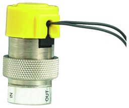
The solenoid used is a Clippard “Mouse” EV Solenoid Valve, which runs about $30 pre-tax pre-shipping in single quantities. This is the single most expensive part of the setup. The valve has a very short travel, and actuates in 5-10 milliseconds, letting very quick bursts of gas through when its active. Since it also has a very short travel, its inherently very quiet (it produces a soft clicking, unlike the loud clack of most gas solenoids).
The Circuit
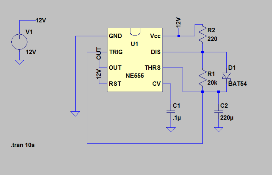
I’m planning on using a version of the 555 timer circuit designed for very low duty cycle applications, which uses a diode to split the on/off timing of the system between two very different values.
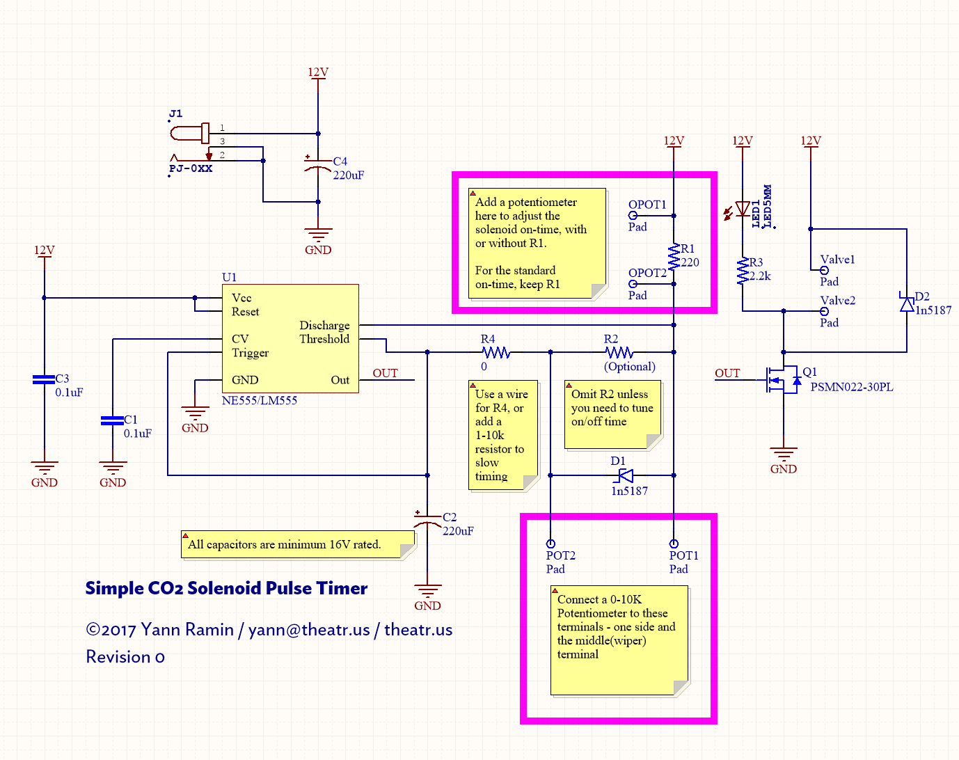
In this case, the “20k” resistor would actually be a potentiometer or a series/parallel combination of a resistor and potentiometer (to tweak the range). The 220 ohm resistor sets the “on” time of the circuit.
The output of this 555 circuit would feed an N-channel MOSFET to actually switch the solenoid on and off. The above is simulated in LTSpice to help tweak values and get in the ballpark of the speed I want. Since the calculations including a diode are a bit more difficult, just using a circuit simulator is the fast way to validate. If you have a copy of LTspice, the simulation file is here: https://theatr.us/images/co2pro/co2timer.asc
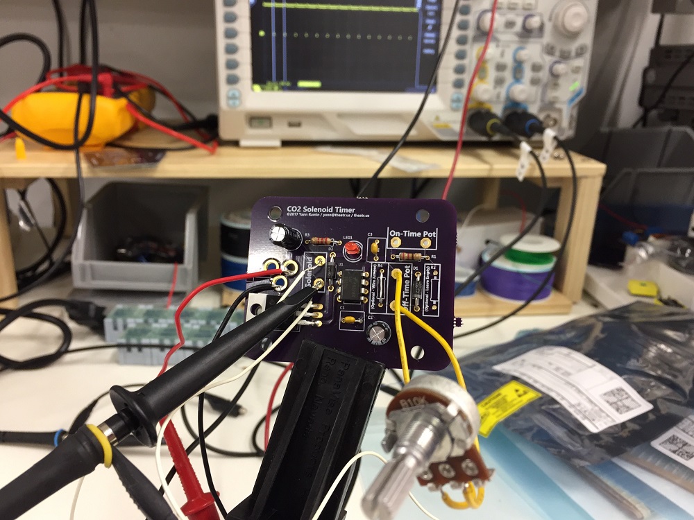
The Assembly
Yes, this does work - its a simple 555 timer after all.
You can grab the boards from OSHPark at your leisure:
https://oshpark.com/shared_projects/kJ0Pkzaz
And the BOM with all of the illustrated parts is on OctoPart: