Some updates for products over at blueacro.com - mirroed from Reef2Reef
I have basic power boards already designed up, and a few sample cases in house. The form-factor is nice, though slightly tall compared to your average power strip. Probably not a major issue, as its a fair bit less wide. I’ll report back when I have some first samples assembled. The power board has a number of provisions, including protection for the relay contacts with inductive loads, without using a plain MOV or other circuit which leaks power. This adds a few dollars of cost per outlet, but ensures the relay will continue working for its entire rated life, no matter what is plugged in, and that the relay fully switches off with light loads.
I have a companion sense board designed to give current per strip using a CT (fully isolated). This will require some calibration when building to ensure an accurate current figure.
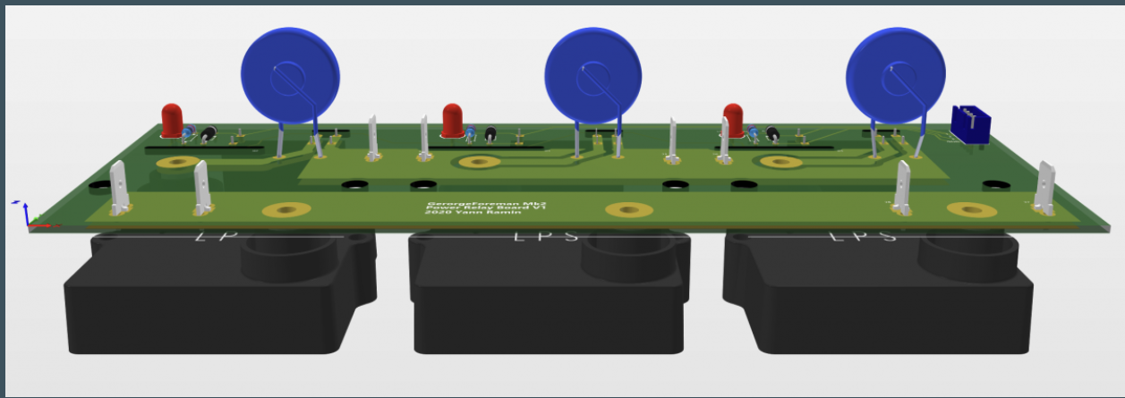
Building things that switch power, and are at high power loads from the wall, means testing extensively when developing and shipping. Part of that is ensuring every outlet can be fully loaded to specification, and the strip is running at maximum power, in addition to providing multiple points of calibration load. About 10 years ago I helped design a number of factory power test fixtures based on high power, non-inductive heat sink mounted resistors, nicknamed “George Foreman” after the line of home grilling appliances. I’m now basically repeating that work with GeorgeForeman, Mk2, which can give up to 15A of load at 120VAC (1800W), at least for some period of time until heatsinks are too toasty for the fans to keep up. The basic premise is a large enclosure, multiple 300W non-inductive resistors, lots of heatsinks, lots of fans, and some relays to switch loads on and off:
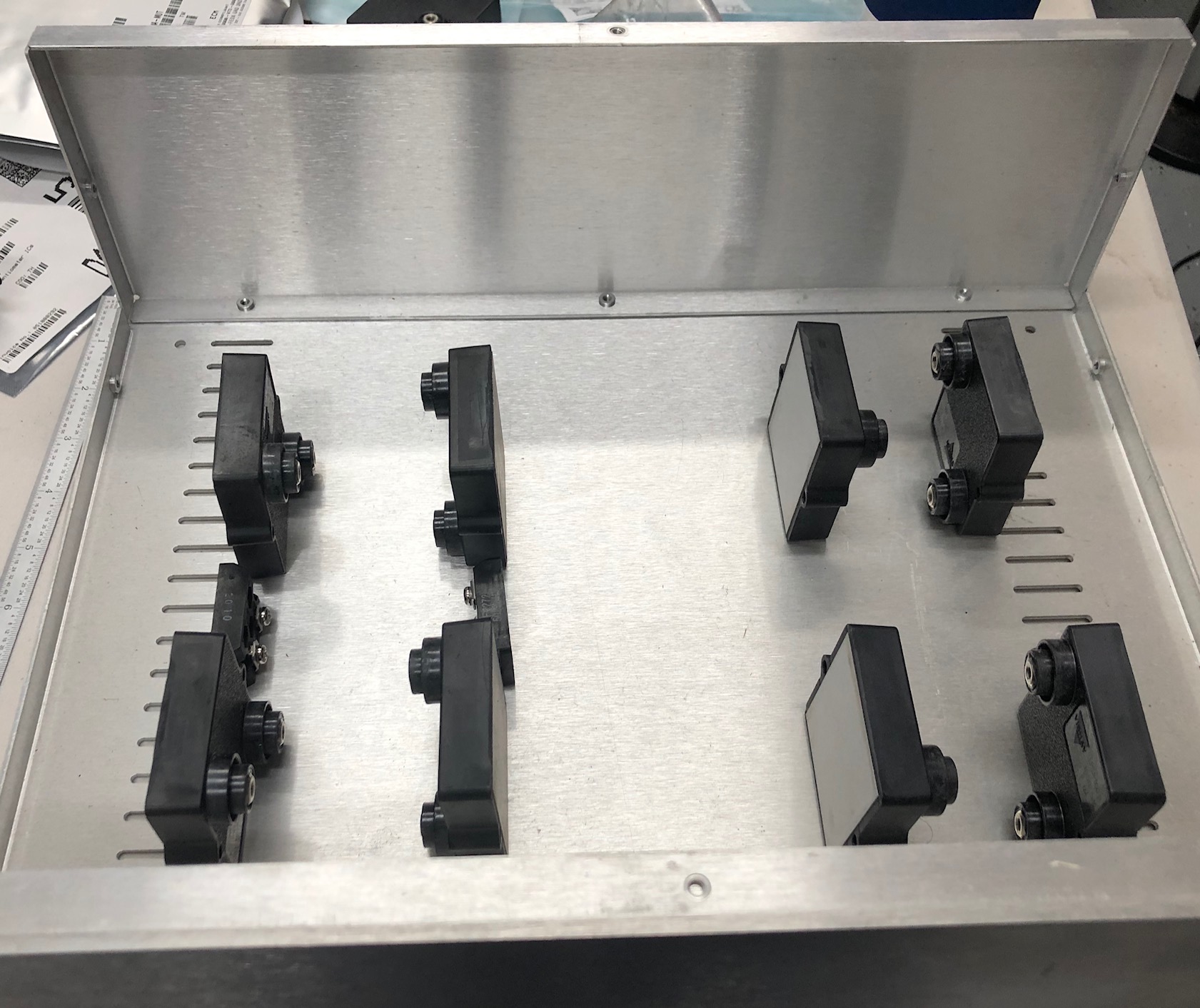
Final count is x12 100ohm 300W resistors parallel switched across 4 heatsinks running the full 12" length of that case, each with a switch board:
Plus 2 much smaller series switched resistors of about 500-1k to allow for low load. Its the world’s most expensive heater, but is much cheaper than giving Chroma a ton of money for a fancier AC load at 5x the price. Power supplied will be on a Instek AP-7100, and a 20A wall outlet for full power runs (since the AC source, despite weight in at 100lbs and connected up to a 240V outlet, has a 1000VA / 8A limit).
Inductive loading needs to be tested as well, and I’m looking at options (aka, what large transformers are laying about I can use).
As mentioned in the ReefPi thread, I’ve been doing sensor qualification. Currently the biggest challenge is.. finding labels that will stick to themselves. Super annoying. Some quick teasers:
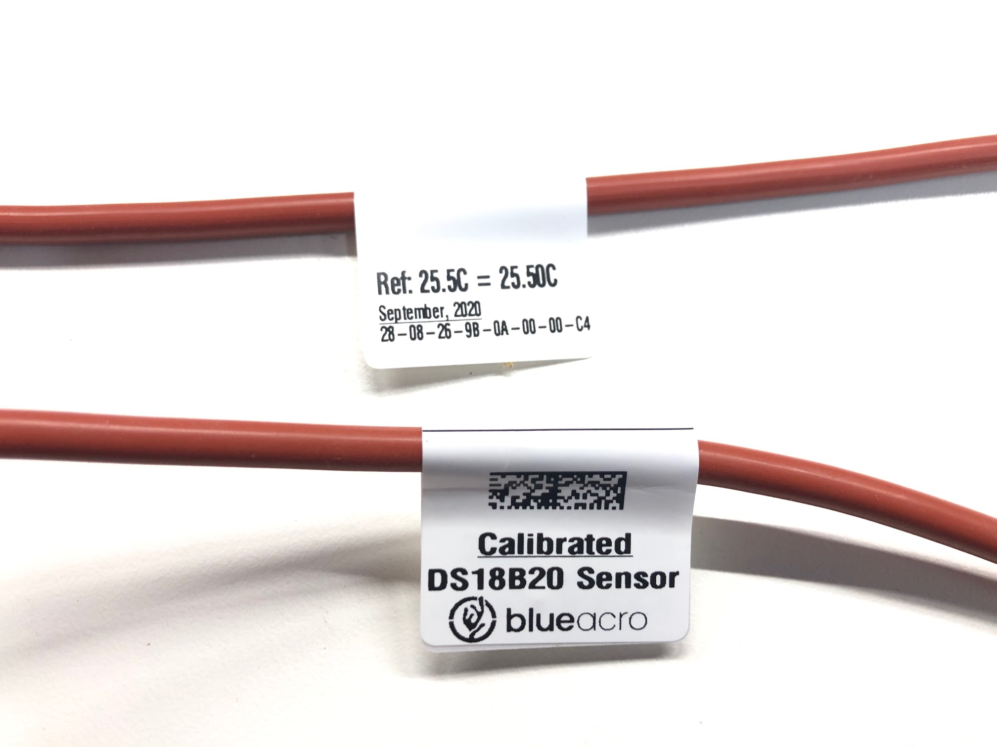
In a batch of 20 sensors, I had 5 sensors outside the 0.5C range, and 1 sensor a whole 1.5C out - and this the “high quality” import option. A ton of other sensors all used fake DS18B20 chips and were even much further out, so as part of figuring out the screening and calibration system went straight to the ewaste pile. Each sensor was in the calibration dry-well for 30min, so its a pretty time consuming process. Keep an eye out on the website for sensors soon, once I get labels working…